Guides / Process
5-Axis CAM Toolpaths: Swarf, Flowline and Multi-Axis Roughing
October 4, 2026
A CAM system turns a 3D model into the moves a machine makes, and on a 5-axis machine there are many ways to do that for the same part. The toolpath strategy decides how long the cut takes, how smooth the surface is, how much the tool wears and how much risk the program carries. Buyers do not write toolpaths, but knowing the three main families helps you read a quote and ask a useful question when a shop’s price or lead time looks odd.
Why toolpaths change when the axes tilt
On a three-axis machine the tool always points straight down. The only choice is where it goes. On a 5-axis machine the tool orientation is a second set of choices. The programmer decides, at every point, how far the tool is tilted and in which direction. That freedom lets the tool cut with a better part of its edge, keep a shorter stick-out and avoid the dead centre of a ball-nose cutter, which cuts poorly because its surface speed at the tip is close to zero.
The price of the freedom is complexity. The programmer must also avoid collisions between the tool holder, the spindle, the fixture and the part. This is why simulation is a normal step in 5-axis programming, covered in collision checking and machine simulation.
Swarf milling
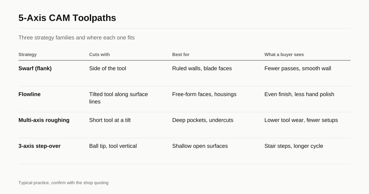
Swarf milling, also called flank milling, cuts with the side of the cutter. It suits surfaces that can be generated by a straight line moving along a curve. Examples are straight-sided walls with a twist, impeller and blade surfaces with ruled geometry, and tapered or drafted walls.
The tool lies along the surface and the rotary axes tilt it as it moves. A single pass can cut the whole height of a wall that would need many stepped passes with a ball-nose cutter. The benefits are shorter cycle time and a finish without stair-step marks. The limits are that the surface must be close to ruled and that the tool side needs to be strong enough to cut the full height. Deviation from a true ruled surface shows up as a form error, so shops check it in the CAM software before cutting.
Flowline milling
Flowline, also called flow or isoparametric, toolpaths follow the natural lines of a surface. Think of the grid of lines on a curved panel, one set running along the length and one across. The cutter follows one set and steps over along the other.
The tool tilts to keep a steady angle to the surface, so the cutting conditions stay even. That gives an even scallop pattern and a predictable finish on free-form shapes such as sculpted housings, moulds and medical implants. Flowline paths often need a good surface model with clean, continuous faces. A model with gaps or messy joins slows the programmer down and can leave visible lines.
Multi-axis roughing
Roughing removes most of the material, so it dominates machine time on many parts. Multi-axis roughing strategies include:
- 3+2 roughing. The part tilts to a fixed angle and the tool cuts a normal pocket path. This reaches undercuts and side features without a long tool.
- Tilted roughing with a shorter tool. The tool is tilted away from the wall so a shorter, stiffer holder can reach deep.
- Plunge or Z-level roughing with tilt. Used where the tool needs to enter a deep cavity from a steep angle.
- Trochoidal and adaptive paths. The tool moves in rounded paths that keep a constant chip load, which is helpful in hard materials such as titanium.
Roughing paths on 5-axis machines are often written so the finishing tool leaves very little stock to cut, which keeps finishing cuts light and the surface even.
How strategy shows up in a quote
| Choice | What it changes | What a buyer sees |
|---|---|---|
| Swarf on ruled walls | Fewer passes, smoother wall | Shorter cycle time |
| Flowline on free-form faces | Even scallop, predictable finish | Less hand polishing |
| 3+2 roughing | Shorter tools, fewer setups | Lower tool wear charge |
| Ball-nose with 3-axis step-over | Stair steps, long cycle | Higher price, rougher finish |
| Full simulation before cut | Fewer surprises | Longer programming, safer first part |
The figures are typical patterns, confirm with the shop. A shop with an experienced programmer will often quote less machine time than a shop that reaches for the default toolpath.
Programming time is part of the price
On a complex part the programming time can be hours or days, and a good share of that goes to checking the program on the simulation. For one-off prototypes the programming may be the biggest line of the quote. For repeat orders it is paid once, so the unit price drops. When you plan repeat orders, say so on the RFQ, and ask the shop to keep the program and the setup sheet. Our guide on moving from prototype to production covers how to plan for it.
Tool axis control
Besides the path itself, the programmer sets how the tool is tilted along it. The common choices are:
- Normal to the surface. The tool axis follows the surface normal. Simple, but a ball-nose cutter then cuts with its dead centre on flat areas.
- Lead and tilt angles. The tool leans forward in the direction of travel by a few degrees and sideways by a few more. This moves the cutting contact off the tip and gives a cleaner cut.
- Fixed axis for 3+2. The tool is held at one angle for a whole region, then re-set for the next.
- Collision-driven tilt. The system tilts the tool only as much as needed to avoid the holder hitting a wall.
Lead angles of 5 to 15 degrees are common in finishing, and the right value depends on the tool, the material and the surface. Smooth control of tool tilt matters because sudden changes in tilt show up as marks on the surface or as sharp motion of the rotary axes.
Step-over, scallop and finish
On a curved surface, each pass leaves a ridge between neighbouring passes, called a scallop. The height of the scallop depends on the tool radius and the step-over between passes. A smaller step-over gives a smoother surface and a longer program. Tilting the tool changes the effective radius at the contact point, which is one reason a 5-axis finishing pass can use a wider step-over than a 3-axis pass for the same finish.
Buyers can use this to understand quotes. A tight finish target on a large curved surface means many passes and a long cycle time. If a surface will be polished or blasted afterwards, a looser machined finish can save money, and the guide on surface finish for 5-axis parts explains how to state that on a drawing.
What to ask a shop
- Which toolpath type do you plan for the main surfaces, swarf, flowline or step-over?
- Do you simulate the full machine with holder and fixture before the first cut?
- Do you keep the program, tool list and setup sheet for repeat orders?
- What is the expected programming time, and is it quoted separately?
- How do you handle a model with gaps or overlapping faces?
What to send with the RFQ
A clean 3D model in STEP format makes programming faster and more reliable. Send the drawing too, marking the surfaces that matter for fit and appearance. If a surface needs a defined finish, give the Ra value and say whether visible tool marks are acceptable. Use the RFQ form to send the files and we match the request with shops that run the right equipment. If you are unsure how to describe the part, our guide on how to write an RFQ for 5-axis machining walks through the fields.
Checklist
- Send a STEP model and a drawing with critical surfaces marked.
- Give a finish target in Ra for each surface that matters.
- Say whether repeat orders are planned.
- Ask which toolpath types the shop plans for the main surfaces.
- Ask whether the program is simulated with the full machine.
Frequently asked questions
What is swarf machining?
Swarf machining cuts with the side of the tool instead of the tip. The tool lies along a ruled surface such as a straight-sided wall or a blade face, and the rotary axes tilt it as it travels. One pass can replace many stepped passes, and the finish is smoother.
What is a flowline toolpath?
A flowline toolpath follows the natural flow lines of a surface, usually along its parametric directions. The cutter tilts to keep a steady contact with the surface, so the scallop pattern is even and the finish is predictable on free-form shapes.
Does the CAM system matter to a buyer?
The brand rarely matters. What matters is whether the shop can simulate the full machine, prove the program on a first article and repeat it on later orders. Ask about those points, not the software name.
Need a quote for this part?
Send the drawing. We match you with up to 3 5-axis shops and reply within 24 business hours.
Get matched with a 5-axis shop