Guides / Process
Collision Checking and Machine Simulation Before a 5-Axis Run
October 21, 2026
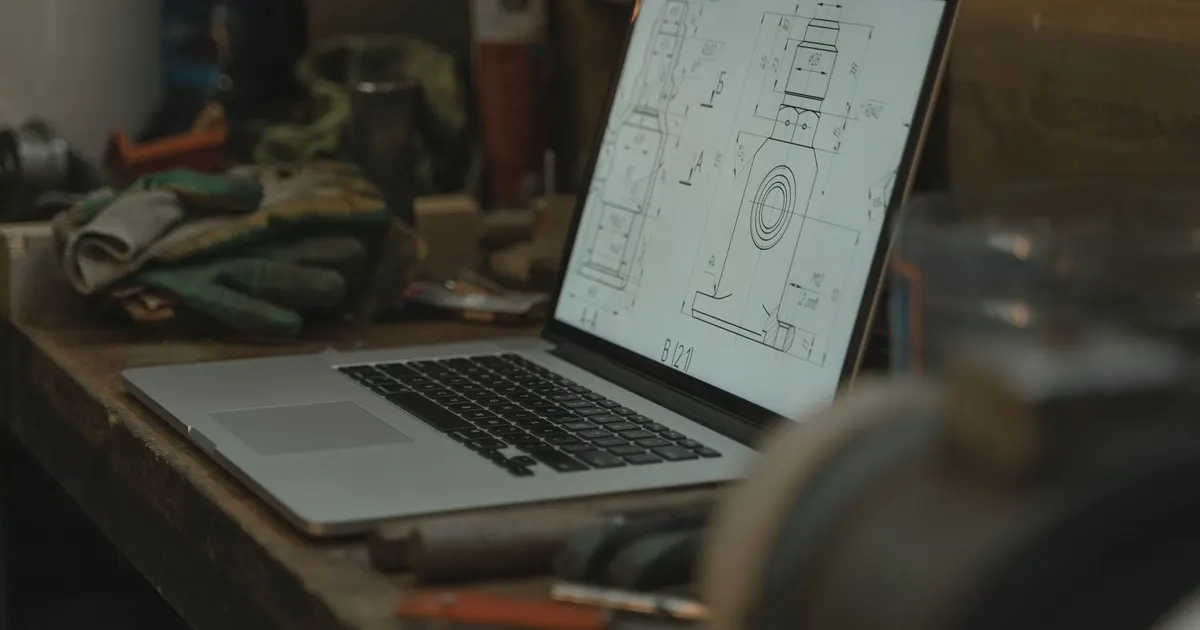
A 5-axis machine can destroy itself in a fraction of a second. The tool, the holder, the spindle nose, the fixture and the part all move relative to each other, and some of those positions only occur at odd tilts in the middle of a program. Simulation is how a shop checks the whole program on a computer before the machine moves. For a buyer it matters because a crash scraps the part, can damage a machine that other jobs share and pushes the delivery date.
What simulation checks
Not every simulation checks the same things. The levels run from simple to complete.
Toolpath preview in the CAM system. The software shows the tool moving along the path over the part model. It catches gouges into the part and gross errors, but it usually does not know the real machine.
Material removal simulation. The software removes stock as the tool moves and compares the result with the model. It shows leftover material and areas where the cutter cut too deep.
Full machine simulation. A digital model of the real machine, with its axes, travel limits, spindle, table, covers, tool holders and fixture, runs the exact code the machine will run. This catches collisions between any two bodies and shows where an axis would reach its limit.
The last level is the one that prevents crashes. A shop that simulates only the toolpath is checking half of the risk.
Collisions to look for
The typical collisions on a 5-axis machine are:
- Tool holder or spindle nose against the part or the fixture when the tool tilts.
- Fixture or part against the machine table, covers or the spindle housing when the table tilts.
- Tool shank against a wall of a deep pocket.
- Rapid moves between cuts that sweep through the part when the rotary axes turn together.
A tool that is correct at the cutting point can still crash on the way there, so the simulation must include the connecting moves, not just the cuts.
Axis limits and flips
Rotary axes have limits. A tilting axis may reach, for example, about 110 degrees in one direction and less in the other. A rotary table can spin without limit on some machines and have a wrap range on others. When a program asks for an angle outside the range, the control stops the machine or swings the axis the long way around, which can crash or leave a witness mark.
Another known problem is the position where the tool axis is nearly vertical. There the rotary axis that spins the part can flip by a large angle for a tiny move, which shows up as a sudden jerk or a mark on the surface. Good programmers avoid these positions or control the flip, and simulation reveals them before they cost a part.
What simulation cannot catch
Simulation shows what the model contains. It cannot catch problems that the model does not know about.
| Problem | Why simulation misses it |
|---|---|
| Wrong tool length in the control | The model uses the intended length, not the entered one |
| Fixture placed a few millimetres off | The model assumes the fixture position |
| Stock larger than the model | The simulation starts with the planned stock |
| Chips packed in a pocket | The model is clean |
| Tool deflection under cutting load | The model treats the tool as rigid |
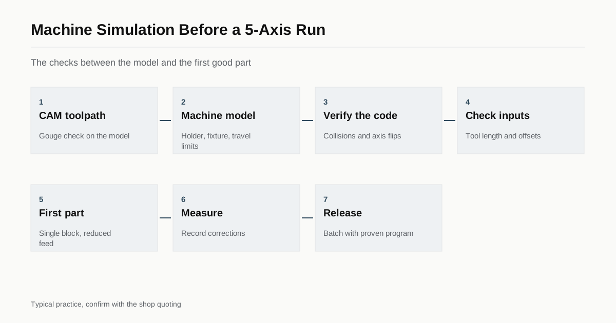
This is why shops pair simulation with a careful first run: tool lengths measured and checked, work offset probed, the first pass at low feed and a hand on the feed override. For more detail on what a first article should show, see inspecting a 5-axis part.
The cost of skipping it
For a simple part with a short program, a shop may decide that a full simulation costs more than the risk. For a part with tilted features, deep pockets, long tools or expensive material, the decision is easier. A crash on a titanium blank or a forged blank that took weeks to source costs far more than the extra hour of simulation.
A buyer rarely sees this decision, but you see the result. A shop that simulates properly may quote a little more programming time and deliver fewer surprises. A shop that skips it may quote lower and take risks with your material, schedule and tolerances.
How it ties to other parts of the process
Simulation depends on good inputs. The fixture needs a model, the tools need holder models and the CAM output must match the machine. It works best when the shop uses the same machine model for programs it runs often. Our guides on workholding and CAM toolpaths explain two of the inputs that decide how reliable the check is.
Building a trustworthy machine model
A simulation is only as good as the model behind it. A reliable model includes the real travel limits of each axis, the position of the rotary pivots, the size and shape of the spindle nose and the covers, and the tool holders actually used on the job. The fixture and the stock must be modelled too, at the size they are on the day. Shops that run the same machine every day build the model once and reuse it, adding a new fixture model for each job.
Some shops use the simulation that comes with the CAM system. Others use a separate verification program that reads the final machine code, not the toolpath. The second approach is stronger because it checks what the machine will run, including any change introduced by the post processor. If a shop only checks the toolpath, ask whether the code itself is verified before the run.
What a good proving routine looks like
A careful first run on the machine usually follows a pattern.
- Check that tool lengths in the control match the tool list.
- Probe the work offset and compare it with the expected value.
- Run the program in single-block mode with rapid moves reduced, watching the first approach to each new area.
- Cut at reduced feed on the first pass, then raise it.
- Stop after roughing to check the stock left, and again before the finishing pass on critical faces.
- Measure the first part and record corrections.
This takes more time than pressing start, and it is where much of the programming and proving time in a quote goes. For production parts the same steps are done once and the result is stored with the program, so the second order starts from a proven setup.
Simulation and singularities
Near the position where the tool is vertical, the rotary axis that spins the part can change by a large angle for a very small move of the tool. The control may then swing that axis quickly, and the feed at the tool tip drops or the axis jerks. Programmers avoid such moves by changing the tilt slightly or by cutting those areas with a different strategy. Simulation shows the axis angles along the whole program, so a flip from 0 to 180 degrees is visible before it leaves a mark on the part.
What to ask a shop
- Do you simulate the program with a model of the real machine, including holder and fixture?
- Do you check axis limits and rotary flips?
- How do you verify tool length and work offsets before the first cut?
- How is the first part run, for example at reduced feed?
- Do you keep the simulation file for repeat orders?
You can add these questions to a request through the RFQ form, and we pass the questions on to the shops that receive your request.
What to send to support the check
- A STEP model of the part and of any fixture you supply.
- The raw stock size and form.
- Datum scheme and the faces that must be cut in one setup.
- Features near walls or in deep pockets that need long tools.
Checklist
- Ask whether simulation includes the full machine, holder and fixture.
- Ask how tool length and offsets are verified on the machine.
- Ask how the first part is run.
- Send models of any fixture you supply.
- Ask for the first article report before the batch.
Frequently asked questions
Why is simulation more important on 5-axis than on 3-axis machines?
On a 3-axis machine the tool always points down, so a collision is easy to see. On a 5-axis machine the tool, holder, spindle and fixture can all swing into each other at tilted angles that are hard to picture. Simulation shows what the eye cannot.
Does simulation remove the need for a first-article check?
No. Simulation shows motion and geometry as modelled. The real machine may differ in tool length, fixture position or offsets. Shops still run the first part carefully, often at reduced feed, and inspect it before the batch.
Should I ask a shop which software it uses?
The brand matters less than the scope. Ask whether the simulation includes the full machine model, the tool holder and the fixture, and whether it checks axis limits. A simulation of the toolpath alone misses many collisions.
Need a quote for this part?
Send the drawing. We match you with up to 3 5-axis shops and reply within 24 business hours.
Get matched with a 5-axis shop