Guides / Materials
Machining Carbon Fiber and Composite Parts on 5-Axis Machines
October 7, 2026
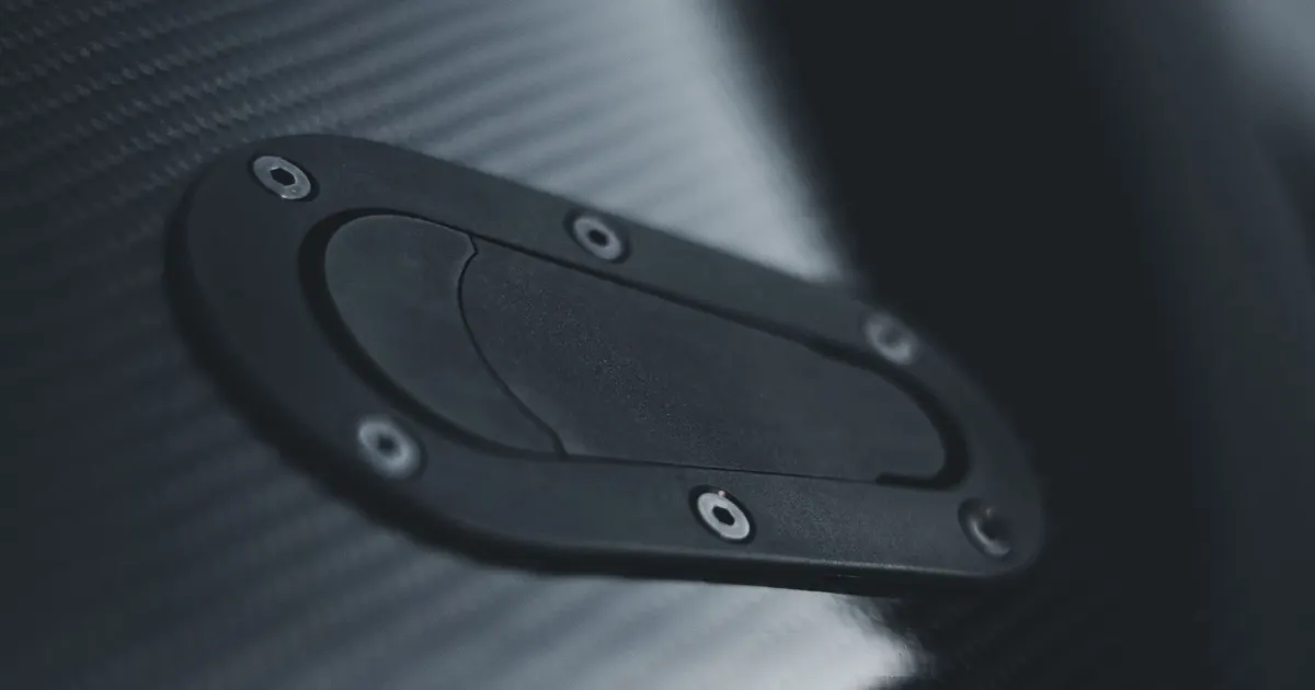
Carbon fibre reinforced plastic, or CFRP, is made by moulding. The part comes out of the mould with rough edges, extra flange and no holes, so almost every composite part is trimmed and drilled after curing. That secondary work is machining, and it behaves nothing like metal cutting. Fibres are abrasive, the resin softens with heat and the layers can separate if the tool is dull or pushes the wrong way. Parts are often curved, so trimming along a 3D edge is a natural job for a 5-axis machine.
What goes wrong in composites
Four defects account for most rejected composite parts.
- Delamination. The layers peel apart at the entry or exit of a cut, often around holes.
- Fibre pull-out and fuzz. Fibres are pulled instead of cut, leaving a ragged or hairy edge.
- Resin burn. Heat softens or burns the resin, leaving a discoloured edge and weakening the bond. Epoxy resins soften at moderate temperatures, often somewhere between 120 and 180 degrees Celsius depending on the system.
- Rapid tool wear. Carbon fibres wear the cutting edge fast, and a worn tool causes the other three defects.
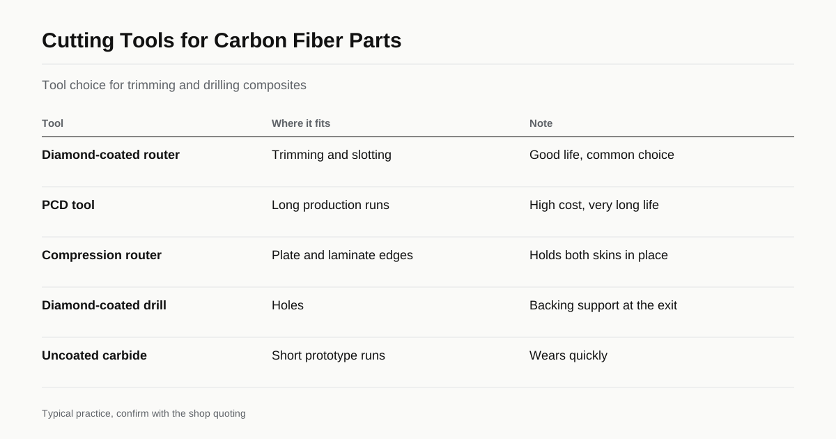
Tools used
| Tool | Where it fits | Note |
|---|---|---|
| Diamond-coated carbide router | Trimming and slotting | Good life, common choice |
| Polycrystalline diamond (PCD) tool | Long runs | High cost, very long life |
| Compression router (up and down cut) | Plate and laminate edges | Pushes fibres in from both faces |
| Diamond-coated drill | Holes | Often with a backing support at exit |
| Uncoated carbide | Short prototype runs | Wears quickly |
Tool geometry for composites differs from metal. Sharp edges, fine-grained substrates and tool designs that shear fibres cleanly are the focus. A shop with a composite programme usually has a tool stock set aside for it.
Dust and cleanliness
Composite dust is fine and hard to contain. It is a health risk for workers and it is conductive, so it can cause faults in the electrical cabinets and encoders of a machine. Shops control it with extraction at the tool, a vacuum shroud, enclosed cabins and regular filter cleaning. Some shops use a dedicated machine for composites, since dust from carbon fibre must not mix with coolant systems for metals. Dry cutting is common because wet cutting can draw moisture into the laminate, and any wet work has to be agreed in advance.
A buyer cannot see these arrangements but can ask. A shop that has a dedicated composite process will describe its extraction without hesitation.
Fixturing
Composite parts are thin and curved, so ordinary vises do not work. Typical solutions are:
- Vacuum fixtures. A machined or moulded nest holds the part by suction.
- Trim fixtures made from the mould shape. The part sits in a shaped support so it cannot move.
- Clamps on sacrificial areas. Clamps hold flange material that will be removed.
- Backing plates for drilling. A support under the exit side prevents delamination.
Fixture cost can be the biggest line in a short run. The guide to workholding for 5-axis machining explains the general options, and the composite case adds the need for gentle, distributed support.
Why 5-axis
On a moulded shell, the edge to trim follows a 3D curve and the faces slope in all directions. A 5-axis machine tilts the tool to stay normal to the surface and keeps the cutting side of the tool in contact with the edge. Holes are drilled perpendicular to the local surface, which gives the right bearing contact for fasteners and reduces breakout. A 3-axis machine could do this with many setups or a custom fixture for each angle. Programs are usually written from the model with flow-style paths, as described in 5-axis CAM toolpaths.
Tolerances and finish
Trimmed composite edges typically hold around plus or minus 0.1 mm without difficulty, and plus or minus 0.05 mm is achievable with a good fixture and a sharp tool. The limit is often the part, which can spring after release from the mould. Hole position tolerance depends on how well the part is located. Edge finish should be specified: sealed with resin, left as cut or sanded. Our tolerance guide shows what features can hold on metal, and composites usually need a slightly looser approach.
What drives the cost
- Tool wear and the price of diamond tools.
- Fixture design and build for each part shape.
- Dust extraction and cleaning time.
- Slow feeds on thick or multi-material laminates.
- Inspection of edges and delamination, sometimes with ultrasound for critical parts.
Cutting strategy for edges and holes
Trimming edges is a matter of keeping the tool sharp, the feed steady and the cutting direction right. Compression routers with both up and down helical flutes hold the top and bottom layers of a laminate in place, so the edge stays clean on both faces. Sharp two-flute diamond-coated tools suit thin laminates. The tool should keep moving, since dwelling at a corner burns the resin.
Holes are drilled with tools made for composites, which have sharp points and special flute designs, and a backing plate or a controlled feed at exit prevents breakout on the far face. Large holes are often milled by circular interpolation with a small tool, which gives a better hole and less delamination than a large drill. On a curved part, the 5-axis machine tilts the tool normal to the local surface for each hole. Countersinks and counterbores are cut the same way, with the depth set against the real surface.
Sandwich panels and mixed materials
Many composite parts are sandwich panels with a honeycomb or foam core between thin skins. These cut differently from solid laminate. The skins are thin and easy to delaminate, and the core is crushable, so the tool must cut cleanly without pulling skin from the core. Edges often need sealing with resin or potting around inserts. Parts that combine composite and metal, such as a carbon plate with a bonded aluminium insert, need a tool plan that handles both without damage, and often a separate pass for each material.
Inspection
Composite parts are checked for dimensions with a CMM or a scanner and for defects by eye and by tap test or ultrasound where the design calls for it. Edge quality is judged against a defined limit, such as fibre fuzz no longer than a given length and delamination no deeper than a given distance. The limits must be written, because composite edges are rarely perfect. Our guide on inspecting a 5-axis part describes the measuring side, and the composite case adds the visual and non-destructive checks.
What to send with the RFQ
- Material: carbon, glass or aramid, resin system and thickness.
- Part form: flat plate, moulded shell or sandwich panel with core.
- The trim line and hole positions from the model.
- Edge finish and acceptance limits for delamination and fuzz.
- Whether you supply the mould shape for a trim fixture.
Use the RFQ form and mention that the part is composite so we match it to a shop with the right extraction and tools.
Checklist
- State fibre, resin, thickness and layup type.
- Send the 3D model with the trim line.
- Give edge condition and delamination limits.
- Ask about dust extraction and dedicated tooling.
- Ask who builds the fixture and who owns it.
Frequently asked questions
Why does carbon fiber need special tools?
The fibres are very abrasive and wear steel and ordinary carbide quickly. They also tear instead of cutting cleanly if the edge is dull, leaving fuzzy edges and delamination. Diamond-coated or polycrystalline diamond tools and compression-style cutters keep the edge clean.
Is carbon fiber dust a hazard?
Yes. Fine dust irritates skin and lungs and is electrically conductive, which can damage machine electronics. Shops use extraction at the cutter, enclosures and filters, and keep composite work separate from other materials where possible.
Can a 5-axis machine cut a composite part from a flat plate?
Yes, for flat plates, but the larger gain is on moulded 3D parts such as shells and panels, where a 5-axis machine follows the curved surface to trim edges and cut holes normal to the surface in one setup.
Need a quote for this part?
Send the drawing. We match you with up to 3 5-axis shops and reply within 24 business hours.
Get matched with a 5-axis shop