Guides / Industries
5-Axis Machining Impellers and Blisks: Process and Inspection
October 17, 2026
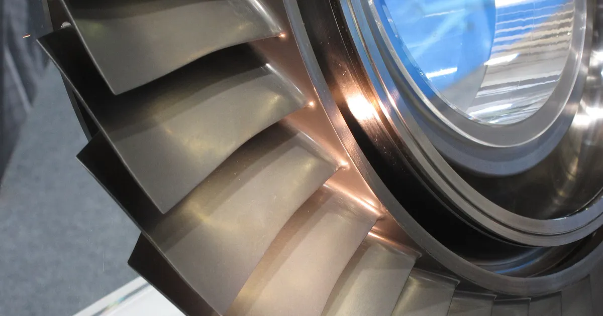
An impeller looks simple in a picture and is among the hardest shapes to machine. The blades are thin, twisted and close together, the passages between them narrow toward the hub and the surfaces must be smooth, because they guide the flow. These parts are made from solid on a 5-axis machine, with a dedicated approach to roughing, finishing and inspection. For a buyer, a clear understanding of the steps explains why prices are higher than for prismatic parts and which numbers on the drawing drive the cost.
What the part is
Impellers are used in centrifugal pumps, compressors, turbochargers and blowers. Blisks, short for bladed disks, are rotor stages of gas turbine compressors where the blades and the disk are cut from one piece. Both have curved blades attached to a hub, and both need accurate blade shape and smooth surfaces.
Typical materials include:
| Material | Typical use |
|---|---|
| Aluminium alloys such as 2618 and 7075 | Turbocharger and small compressor wheels |
| Stainless steel such as 17-4 PH | Pumps and industrial compressors |
| Titanium Ti-6Al-4V | Aerospace compressors, weight-critical wheels |
| Nickel alloys such as Inconel 718 | Hot sections and high-stress wheels |
The material changes the cutting data, tool life and price by a large factor. Our articles on titanium and aluminium describe the material behaviour.
The process in steps
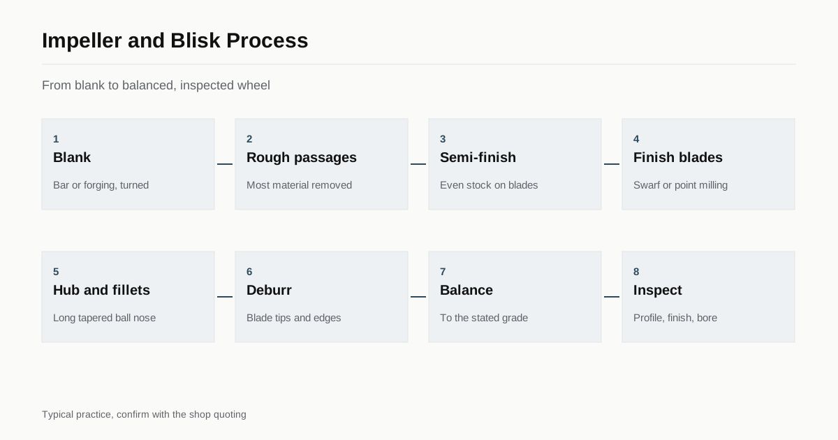
Most impellers follow the same order.
- Blank. A bar, forging or rounded blank with turned diameters, often finished on a lathe first.
- Roughing the passages. Large tools remove most of the material between the blades with plunge or pocket strategies, leaving an even allowance.
- Semi-finishing. The allowance is reduced and evened out, so the finishing tool sees little variation.
- Finishing the blades. The tool cuts the blade faces, with swarf (flank) or point-milling paths. Blade thickness is controlled carefully, and thin blades are cut in steps to limit vibration.
- Finishing the hub and fillets. Long tapered ball-nose tools or barrel-shaped tools finish the hub surface and the blend radius at the blade root.
- Trimming and deburring. Blade tips and edges are finished, often by hand or with controlled abrasive processes.
- Balancing. The rotor is balanced to a defined grade, and material is removed from non-critical places if needed.
The toolpath types in steps 4 and 5 are described in 5-axis CAM toolpaths.
Why it is hard
Three issues dominate.
- Reach. The tool must get into a narrow passage, so the tool is long and slim, and long tools deflect and vibrate.
- Thin blades. A blade a millimetre thick or less flexes under the cutting force. It moves away from the tool, springs back and leaves an uneven wall.
- Collision risk. The tool, holder and spindle are close to several blades at the same time. Simulation of the full program is a normal step, as covered in collision checking and machine simulation.
Shops use short tools where possible, lean the tool to reduce the stick-out, take light finishing passes and sometimes use damping tool holders or special fixtures to support the blades.
Inspection
Inspection of an impeller checks both the form and the surface.
| Check | Method | What it shows |
|---|---|---|
| Blade profile and thickness | CMM scanning or optical scanning | Section shape against the model |
| Leading and trailing edge | Profile scan or optical comparator | Edge radius and shape |
| Hub and bore diameters | CMM or bore gauge | Fit to shaft |
| Surface finish | Contact profilometer | Roughness on flow surfaces |
| Balance | Balancing machine | Residual unbalance against a grade |
| Surface condition | Visual or dye penetrant | Cracks, smeared metal, burrs |
Blade tolerances are often a few hundredths of a millimetre on the profile, but the figure comes from the design and should be stated on the drawing. The guide to inspecting a 5-axis part explains how shops confirm that a part matches the model. Aerospace parts may add non-destructive tests and process records, which the buyer must request, as the shop cannot assume them.
What drives the cost
- Material and blank type, including forged blanks.
- Number and height of blades.
- Blade thickness and tolerance on the profile.
- Surface finish on flow surfaces.
- Balance grade and inspection scope.
- Programming and proving time on the first part.
The first part of a new impeller is much more expensive than the repeat because of programming, simulation and fine tuning. If you plan to order again, say so in the RFQ. A shop that expects volume can spread the engineering cost.
Reading an impeller drawing
An impeller drawing usually includes a model reference and a table of blade sections. Each section gives the blade profile at a given radius, with tolerances. Other callouts include the hub profile, the bore with its fit and keyway or spline, the blade tip diameter and the balance requirement. A buyer who sends a STEP model and a drawing with this table gives the shop what it needs to program and to inspect.
Some drawings leave blade thickness and shape to the model. Where the tolerance is not stated, ask the designer to state it, since a shop cannot guess what the flow design needs, and a general tolerance rarely suits a blade surface.
Open and closed impellers
Open impellers have blades exposed, with no shroud, and can be cut from one side. Closed impellers have a cover that encloses the passages, which a milling machine cannot reach. These are made by other means, such as welding or brazing two machined halves, casting or additive manufacture followed by finishing. When a drawing shows a closed impeller, ask the shop how it plans to make it, since the process changes the price and the lead time. Many impellers in turbochargers and compressors are open, which suits 5-axis milling from solid.
Tool wear and process control
Impeller work uses long tools at tilted angles, and tool wear shifts the blade surface. Shops control this by changing finishing tools at set intervals, measuring tools on the machine, probing the blank and checking a blade section on the machine before the final pass. For high-value parts such as titanium blisks the shop may measure a section after each blade or after a set of blades. These checks add time to the cycle but protect parts that took days of machine time to reach that stage. They are the reason a first impeller is much more costly than the second, and why buyers should ask about repeat quantities at the start.
What to send with the RFQ
- A 3D model, preferably in STEP, and a drawing with tolerances for the blade profile.
- Material and specification, with certificate needs.
- Balance grade and the standard used.
- Surface finish on flow surfaces.
- Quantity and repeat plan.
- Operating context, such as speed range and fluid, if the shop needs to understand risk.
If the part is for aerospace use, the guide on 5-axis machining for aerospace parts lists the usual documents. Send the files through the RFQ form.
Checklist
- Send the STEP model and a drawing.
- State the material and the certificate type.
- Give blade profile tolerance and the balance grade.
- Give the finish for flow surfaces.
- Say whether repeat orders are planned.
Frequently asked questions
What is the difference between an impeller and a blisk?
An impeller is a rotating wheel with blades that moves fluid or gas, used in pumps, compressors and turbochargers. A blisk is a bladed disk, a rotor where the blades and the disk are one machined piece, used in gas turbine compressors. The machining logic is the same.
Why can't an impeller be made on a 3-axis machine?
The blades are curved and overlap in the flow passage, so the tool must approach at changing angles and tilt around the blade to reach the hub and both sides. A 3-axis machine cannot reach those faces without gouging the next blade.
How long does it take to machine an impeller?
From a few hours for a small aluminium wheel to several days for a large titanium or nickel alloy blisk. Material, blade count, blade height and the surface requirement decide. Ask the shop for a time estimate by operation.
Need a quote for this part?
Send the drawing. We match you with up to 3 5-axis shops and reply within 24 business hours.
Get matched with a 5-axis shop